Chapter 13
NBTV Sawtooth Test Generator
To get the best from an NBTV signal it is important to use the full dynamic
range of the signal with no crushing at black level or peak white. To check the
linearity of a video path it is usual to use either a staircase or sawtooth test
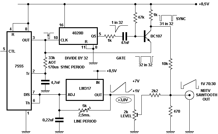
signal. The circuit described is a free standing NBTV sawtooth generator
conforming to the standard of 1volt output level and complete with 31 line sync
pulses.

The 7555 timer and LM317 regulator form a linear sawtooth generator. Two timing
capacitors are employed, one setting the active line time which may be trimmed
by the pot, the second sets the line sync duration. The circuit is un-usual in
that the LM317 performs two roles. It acts as constant current genera-tor to
linearly charge the 0.22 mF capacitor, and also provides a very low output
impedance.
The 4020 counter is used as a divide-by-32 fed from line pulses. The grounded
base transistor differentiates the falling edge from Q5 of the 4020 and gates
out one sync pulse in 32, the output from the gate being non-inverting. The
remaining 31 sync pulses are mixed with an attenuated sawtooth to form a
standard 70%-30% 1 V NBTV signal and delivered at a nominal 470 Ω
impedance.
The circuit is sensitive to variations in the supply rail and the prototype was
driven from another LM317 set to a nominal 8.5 V allowing use of a 12V supply.
If a regulated supply is employed there is no need for this second regulator.
