Chapter 17
Camera - Monitor assembly
Les Robotham and R. Pedro have developed this project over a number of years.
The unit itself forms a self-contained combined camera and monitor, which at a
later date can be modified to produce video signals for external equipment.
No synchronising is required as the monitor and camera share the same disc.
A special disc is used having the holes distributed over one and a half turns to
ensure the image on the viewing section is the right way round. Construction is
not critical but it is important that external light entering the disc area is
kept to a minimum. Areas within the camera and detection head are sprayed matt
black to reduce reflections. Many variations have been made of this unit
including the 'hidden disc' 'biscuit tin' method where the disc is completely
enclosed, the only apertures being for the viewing area and the lens and
detection head.
What you will need for this project:
- Enclosure for disc and mounting base or cabinet
- Special one and a half turn spiral disc ( club sales )
- Power supply unit for motor and electronics
- Cassette motor. ( club sales )
- Motor speed control electronics
- LED cluster and LED driver electronics as in the monitor
- Detector head assembly including electronics
- A suitable lens ( see later )
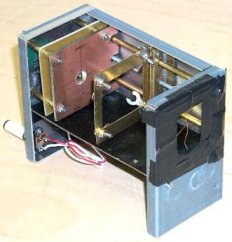
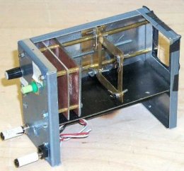
Enclosed disc and cabinet
Top view of cabinet, in the right half the monitor part, in the left half the
camera part.
The disc is enclosed by an internal partition and the front of the cabinet with
rectangular cut-outs.
Whilst the design is not critical, stray light must be kept out of the area
between head amplifier section and the disc. This is achieved by spraying all
the inside of the box matt black. The advantages of the square box are that
different scanning formats can be achieved, either by changing the direction of
motor, reversing the disc or positioning the box in another plane.
This box contains all the sub-assemblies, and can also house the power supply,
if you decide to build this into the unit. You may however decide to enclose the
disc totally in a light-proof unit and mount all the peripherals on the outside
of the unit.
The disc
The club disc has a spiral of 48 holes over 1½ revolution. The camera
masks the inner 16, the monitor the outer 16 holes. In this way camera and
monitor share the same disc. There is an extra circle of 32 sync-holes at the
rim.
Power supply
A 12-volt regulated power supply is required for the camera-monitor. As pointed
out earlier, extreme care must be taken when working with mains voltages. If
unsure use an 'off the shelf' power supply or seek advice from a more
experienced constructor. The power supply should have a minimum current rating
of 1.5 amps, which will be sufficient to drive all the electronics and a
cassette type motor (via the speed control circuit). Motors of a different type
may require a greater current and possibly a dedicated power supply.
The motor
Whilst in a monitor the incoming video signal controls the speed of the motor,
in a camera the motor speed controls the video signal. Different types of motors
can be used. The speed of an AC motor is governed by the supply frequency and
the number of poles on the rotor. Whilst a dynamo is normally a generator,
applying an AC supply it will act as a motor. At 50 Hz an eight-pole dynamo
will rotate at 750 rpm, which is the correct speed for NBTV. Whilst small motors
of this type are rare, a bicycle dynamo can be used, although it will need to be
turned by hand to start. By using dynamos on both camera and monitor the common
ac supply will keep both units in synchronisation.
The most popular motor used however is the small DC motor 'liberated' from an
old cassette recorder. It is important to ensure the motor has not got an
internal speed regulator fitted. If it has this can be easily bypassed. In its
simplest form a variable DC voltage is applied to the motor to vary the speed.
Improved speed control
The natural tendency of the motor is to slow down as the windings 'heat up'.
This can be prevented by running the motor not by a constant voltage, but by a
constant current. A constant voltage gives the motor a constant speed, but this
is affected by changes in the internal resistance of the motor. A constant
current gives the motor a constant torque. Then the speed is the result only of
the applied current and the friction of the air onto the disc.
The exact motor speed is judged by observing the spokes of a stroboscope disc
glued to the centre of the scanning disc and illuminated by the light from an AC
driven neon or fluorescent tube.
In 50 Hz supply areas an eight spoked strobe is seen stationary at 750 rpm, this
is 12½ Hz. In 60 Hz areas, including the USA and Japan, a 10-spoked
strobe should be used, which will appear stationary at 720 rpm, i.e. 12 Hz.
The parallel resistors of 18O Ω and 27O Ω define the coarse speed.
If the speed is too low, replace the 27O Ω for a lower value, e.g. 18O
Ω, if it is too high, replace the 18O Ω by a resistor of higher
value, e.g. 27O Ω.
Mount the LM317 on a heatsink to prevent it running too hot.
Monitor part
The next parts are the LED cluster and LED driver circuit. They are identical to
the televisor in the previous chapter. The sync pulse circuit and automatic
motor synchronisation circuit are not needed. The video input is connected
directly to the output of the head amplifier, which is a separate unit.
The head assembly
The next module to build is the head assembly. The main case is available for
those in the UK from Maplin. The drawing shows the general layout of the
prototype unit.
A lens mounted in this unit focuses the light onto the photo sensor. A screwed
rod facilitates adjustment of the lens from the outside of the unit. Information
on the required optical arrangement is given in the chapter on Optics and Lenses.
The solar cell and head amplifier
The dome cell is mounted behind the condenser lens directly in line with the
axis of the lens assembly in order to focus correctly. The sensor leads need to
be kept as short as possible with the associated variable load resistor
contained within the same small screening box as the head amplifier. The circuit
has a low impedance output. Patrick de Scheemaecker and Keith Vickers designed
this pre-amplifier circuit.
Owing to the high gain (around 85dB) good RF techniques should be used in the
construction of this amplifier. The 22k variable sensor load enables the input
level to the amplifier to be ad-justed. This affects both the sig-nal and noise
level and acts as a sub-stitute iris control.
Further gain adjust-ment, if neces-sary, can be achieved in the subsequent
video/sync mixer. It is normal that the amplifier takes around ten seconds to
stabilise after switch-on. The video output from this unit, which does not
contain any synchronising signals, could be fed directly into the LED driver
circuit.
Finishing the head assembly
Care should be taken to provide adequate screening. This will help avoid
feed-back, RF pick-up and mains hum problems. A hole just large enough to fit
the dome sensor is needed in the front face of the head amplifier screening box.
Further holes are needed for the +12-volt DC and video output leads, and to
allow adjustment of the sensor load.
To minimise internal light reflection within the head assembly the internal
exposed metalwork must be sprayed matt black. Small spray cans of this are
available from most hardware outlets.