Chapter 4
Building a complete NBTV disc televisor
As with most hobbies the beginner's first question is where do I start? We
recommend you to build first a disc televisor and use the club CDs as a signal
source. From then on it's up to you how comfortable you are tackling the project.
Remember not to take on too much at a time.
When you have a working system you may wish to move on to a camera or an
electronic pattern generator. All the circuits in this book have been selected
for their proven track record. Where possible printed circuit boards are
available to ease construction. The project may be as 'minimalist' as the one
shown here. Peter Smith has constructed a disc televisor to show how simple it
can be.
 |
 |
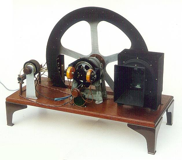
Front view of Peter Smith televisor. The electronics is placed on the
base board. |
Rear view of the televisor. The motor is held on a post with a side
support for the LED cluster. |
And here you see the typical layout of the different components of a Nipkow disc
televisor in top view.
You may however wish to spend even more time and produce a more elegant version
as shown here.
 |
 |
A replica of a Telehor receiver built by Denis Asseman of Belgium. |
A replica of the Baird Televisor built by Peter Smith. |
As you gain experience you may wish to tackle a larger televisor using a more
powerful motor and brighter light source. The circuits to be described can be
adapted for use in a wide range of televisor sizes. The original Baird
televisors were constructed as a piece of furniture, you may feel you wish to
produce some elegant cabinetwork in which to house your televisor.
Building a complete televisor
The parts required for this project are as follows:
- Wooden base
- A pre-drilled disc (available from the club)
- A small DC motor (cassette motors available from the club)
- 12 Volt Power Supply
- Motor drive electronics (PCB available from the club)
- LED cluster as a light source
- A medium size magnifying glass
- LED drive electronics (PCB available from the club)
The most important part of the televisor is the disc; this will determine the
picture quality. Pre-cut discs are available from the club; these will give a
good picture as they have been produced on a numerically controlled machine to
the highest accuracy.
The construction of the televisor is not critical, the cas-sette DC motor is
affixed to the disc in the centre by a push fit plastic coup-ling available from
the club shop. It is then mounted on a frame which allows the disc to rotate
freely.
The LED light source
LED's or Light Emitting Diodes play an important role in the construction of
mechanical NBTV televisors. These now replace the now obsolete large neon lamps.
Choosing the correct LED's is almost as important as producing a good quality
disc. Whilst most LED's on the market will produce a picture of some sort,
bright LED's that modulate without a change of hue will produce a superior
picture. The luminous intensity of an LED is measured in millicandelas (mcd)
normally quoted at a typical forward current of 20 mA. Also the opening angle
of the beam of light is important. The total amount of emitted light is defined
by both. The higher the number of mcd's multiplied by the opening angle of the
beam, and the more LED's of course, the brighter the display will be.
The latest Al-In-Ga-P ultra bright LED's are well suited to NBTV operation. They
can replicate many small conventional bulbs due to their brightness. These LED's
carry warnings as the output light is strong enough to injure eyes when viewed
without a diffuser. Although relatively expensive, due to their efficiency a
cluster can be made of just six devices.
LED's are current operated devices. Normally they are wired in series with a
current limiting resistor. Each LED has a forward voltage drop that depends on
its light colour. For red it is about 1½ volt, for yellow and orange 2 volts and
for blue and white LED's about 4 volts. Orange high brightness LED's combine a
high efficiency with a good visibility and they match more or less the colour of
the ancient neon lamps. When placed in series it is important that the driving
power supply has a potential high enough to overcome the voltage drop of all the
LED's in the chain, else they will not illuminate.
The diagram at the left shows a suggested arrangement for yellow or orange
ultra-bright LED's, two chains of each three devices. Three yellow or orange
LED's in series drop 6 volts, so with a 12 V supply enough voltage remains for
operating the driver transistor. These LED's will withstand 50 mA in each chain,
so the driver has to provide 100 mA for max brightness.
The latest Ga-N devices give pure white display. For white LED's the voltage
drop is higher and the max current per diode is lower, 20 mA. In this case it is
better to place the six LED's in parallel, see at the right.
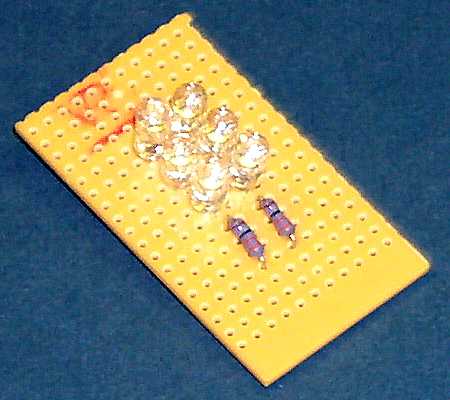
With the absence of a printed circuit board for this part of the project a piece
of 40 mm square stripboard will suffice. A spot face cutter is needed to isolate
the copper area not required. Holes drilled outside the display area will
facilitate mounting.
The LED assembly is mounted behind the disc. A suitably placed diffuser between
the LED's and the viewing area close to the spinning disc will allow uniform
illumination of the display area. Careful positioning of the LED's and the
diffuser is important to ensure the illumination is constant over the display
area. Mount a suitable magnifying glass in front of the disc.
A black viewing tunnel prevents surrounding light from falling onto the glass
surfaces and causing reflections.
Sync separator and LED driver
A composite NBTV video signal is fed into the input; this can be either from a
CD player using one of the club CD's or any NBTV source described in this
handbook. Please note that when using a portable CD player to play one of the
club CDs to use the 'line out' signal and not the headphone output, as some of
the quality is lost in the output audio amplifier.
The description of the circuit is as follows. IC1a and the IN4148 diode DC
restore the NBTV video signal on pin 2 of IC1a. The DC restoration level is set
by the potential on pin 3 of IC1a, i.e. 0 volts. The sync slice level is set at
67mV by the potential divider formed by R1 and R2. A clean positive-going sync
can be taken from pin 7 of IC1b to drive the motor circuit mentioned later. The
1k pre-set on pin 5 of IC2 enables the black level to be adjusted so that only
the picture signal from black to white is used to drive the LEDs. The brilliance
control is adjusted to give about 1 volt peak-to-peak across the source resistor.
This resistor can be changed in value to give the LED current required. The PCB
is available from the club.
Gamma correction
Although the current/brilliance characteristic of an LED is almost perfectly
linear, some correction is provided by two extra source resistors, each in
series with a diode. The 1N4001's resistor boosts the current at the top end
(0.6 V to 1.0 V) of the signal whilst the Schottky diode's resistor affects the
mid-range.
The LED driver circuit will work without these diodes, however they improve the
grey scale appearance of the picture, especially those originating from
electronic camera sources.
Automatic speed control circuit
 *
* values can be changed to suit different motors.
This circuit compares the speed of the disc from a series of 32 holes in the
disc with a reference signal from the sync separator and LED driver board.
The motor speed is automatically adjusted to match the incoming video. We need
to mask off one of the 32 holes on the disc, the hole that passes the opto fork
when the spiral of scanning holes jumps to a new frame.
The only adjustment that may be required is the alignment of the opto speed
sensor. A gap of 8mm was chosen to give enough clearance for a wobbly disc yet
sensitive enough to cope with the small holes in the 12-inch club disc. If a
scope is not available, the output of the sensor can be monitored across R2
using an AVO multi range meter on the 100 V dc range. The voltage should be
greater than 10V when aligned with a disc sync hole and less than 2 V when
between holes. Some external light shielding of PD1 may be required,
particularly on the 12-inch disc, as the sync holes are near the periphery of
the disc and light can leak round the edge.
The component values indicated on the circuit diagram have been selected to suit
the small DC motor and 12-inch plastic disc available from the club. The
components shown with an asterisk can be changed to suit different motors and
supply voltages (see later information on building a larger televisor).
On the motor control PCB provision has been made for either a pre-set or fixed
resistor to act as the opto detector load (R2), to allow for opto fork
components with different characteristics to the types indicated on the diagram.
A 47 k pre-set resistor will be suitable for most alternative types of opto
detectors, including those contained within single package slotted opto switches.
Ideally a scope should be used to adjust the pre-set for best pulse waveform
shape (steep sides and a flat top). Provision has also been made for an on-board
12 V low power regulator for use when the voltage required for the LED and motor
is greater than 12 V. This PCB-mounted regulator is not needed for the basic
televisor where all the 12 V rails can be fed together from an external 12 V
regulated supply. In this case 'Vout' should be linked to 'Vin'.
The two PCB's have been made the same length and can be mounted side-by-side to
enable easy interconnection. A convenient way of connecting the ground planes
and uniting the two boards is to use short pieces of stiff wire to link the
corner mounting holes, as shown in the photo of the minimalist televisor. The
sync and +12V lines also need to be connected by short pieces of insulated wire.
Putting the monitor to work
After building up the circuits and interconnections apply 12 volts DC from the
power supply. Apply a suitable NBTV source to the input and the televisor should
burst into life. Take particular safety precautions with the spinning disc. Once
the video source has been applied the motor should speed up to synchronise with
the incoming video signal and some sort of picture should be seen. Attention
should be taken with the positioning of the opto sensor and transmitter with
relation to the synchronising holes around the disc.
Should the circuit not work, check circuitry and verify with an oscilloscope.
The LEDs should be observed to modulate with the incoming video. Check at the
output of IC1b pin 7 of the LED driver board that there is a 400Hz signal
present for a 32-line system (375 Hz for a 30-line system). Verify that a
corresponding signal is being received by the motor drive system (IC1 pin 3)
from the sync holes in the disc.
Building a larger televisor
The same circuits and general principles as described above can be used to
construct a larger televisor, e.g. using the club 490 mm metal disc, except that
some component values will need to be adjusted to allow for the greater current
required by brighter LEDs and a more powerful motor.
The LED driver circuit can be used to drive higher power LEDs such as the Luxeon
type. To drive a higher current it is necessary to alter the value of the
resistors in the gamma correction circuit in the source of the output FET. The
values given above (33O, 15O and 12O) assume that the LED cluster requires a
peak current of 100 mA. Suitable values for 350 mA, 700 mA and 1.4 A peak
currents are given in the table. The table also gives values for a single source
resistor, to replace the three resistors and two diodes, in cases where gamma
correction is not required.
If two or more LED's are used in series, and the total voltage drop across them
is more than about 6 volts, the supply voltage should be raised to provide a
sufficient operating voltage for the FET. For example, two Luxeon III 700mA
white LED's in series have a total voltage drop of around 8V, and so around 15V
should be used for the LED supply. The FET will require a heat sink at the
higher power levels.
The motor driver circuit can be used with some component changes to suit
different discs and motors. These components are marked with an asterisk on the
circuit diagram. Either a direct drive or belt drive motor system can be used,
the former generally being more straightforward if the motor has adequate
bearings to take the weight of the disc. Belt drive systems can also work well
provided belt slippage is avoided by using suitable pulleys and drive belt.
A motor that has been identified as suitable for directly driving the club 490mm
disc is a Smith Industries motor ref. FHM1207/04. In this case the logic supply,
motor supply and LED supply can all be connected together and powered from a 15V
3A supply (4 to 5 amps on start-up). The on-board 12V regulator should be
installed. Resistor R7 should be reduced to zero ohms. R5 can be changed to 2k2
to give a wider range of speed control, if required. The FET will require a heat
sink.
At the higher peak current levels it becomes necessary to reduce the value of
the resistor (R5) between IC2 pin 6 and the gate of the FET, to avoid unwanted
current limiting. However, this feature can be usefully employed to protect the
LED's from excessive current. Suggested values for this resistor are given in
the table.