

Three photographs and two drawings of Klaas Robers' 10 watt, 29 MHz all tube
NBTV transmitter as published in NBTV Newsletter Vol.29 No.2.
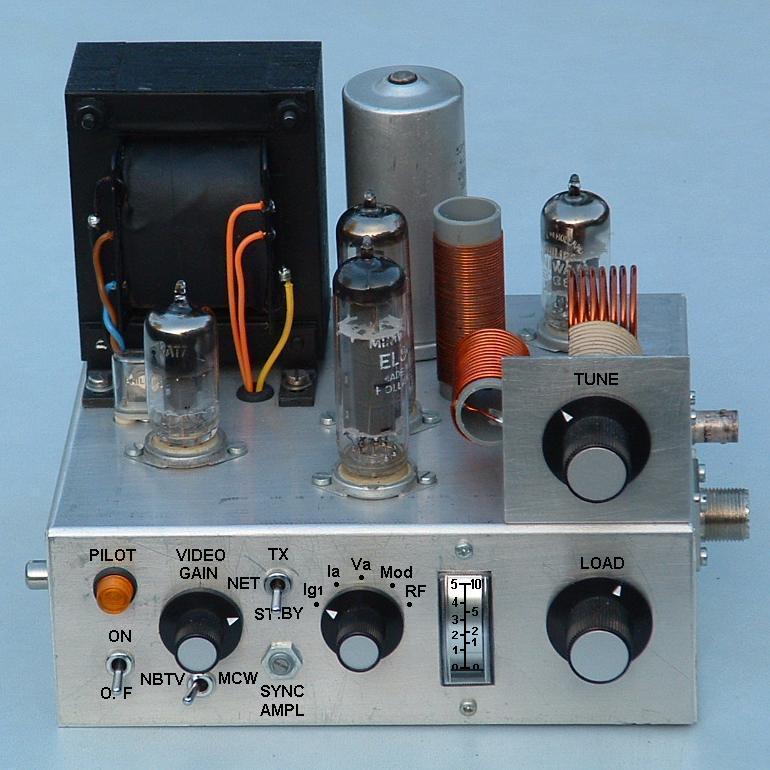
Front view and controls of the 10W (peak sync) tube transmitter.
Click on the photo for a better view.
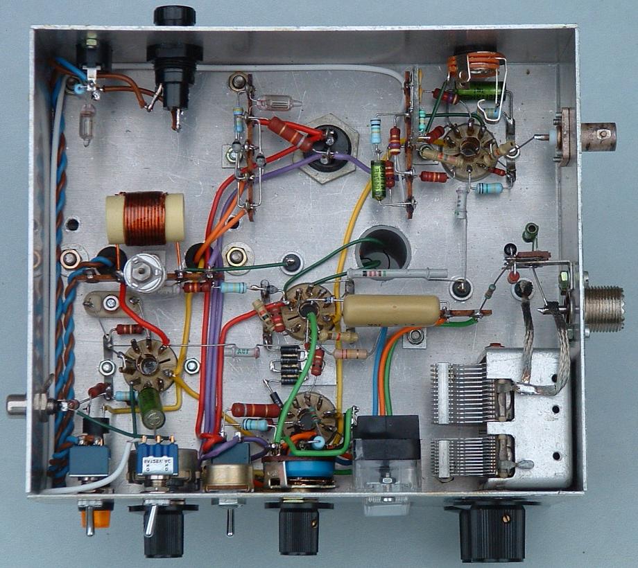
Bottom view inside the chassis. See that two small neon lamps are mounted that
light up when dangerous voltages (230 volt AC and/or 400 volt DC) are present
under the chassis.
For reasons of recognisability this photograph is mirrored.
Click on the photo for a better view.
Top view of the transmitter assembly.
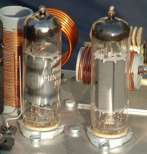
EL83 final transmitter tube . . . . EL84 video
modulator tube
and behind them the output pi-filter for 29 MHz.
Observe the
neutralisation capacitor (wire) left of the EL83.
Circuit diagram of the 29 MHz all tube NBTV transmitter.
Click on the diagram
for a larger and sharper view.