Chapter 3
Typical NBTV EQUIPMENT
Examples of common NBTV equipment are shown. This is not an exhaustive list of
all methods used but highlights most utilised systems.
Nipkow Disc
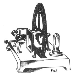
Figure 1 shows the most common system in use, and indeed the one used by the BBC
experimenters of the 1920's and 30's period and Baird in his commercial
televisors. The Nipkow disc named after the German designer Paul Nipkow
comprises of a flat circular disc with equi-spaced holes drilled to form a
spiral. When rotated, a modulated light source behind the disc would shine
through the scanning holes to display a picture when viewed from the disc front.
Should the modu-lated light source be exchanged for a photo sensor device then
the system could be used as a camera. One variation of this system was to fit
lenses in the scanning holes. Separate holes around the circumference of the
disc facilitate synchronising the disc to the incoming video signal. One
limitation of pictures developed or received on a Nipkow disc system was the
keystone distortion caused by the curved image that was scanned in an arc. This
was not a problem if a similar scanning disc was being used at the transmitting
end, but for the early transmissions the BBC used a mirror drum scanner, which
scanned a non curved picture. Most viewers using the Nipkow disc based Baird
"Televisor" accepted this.
Aperture Drum
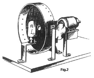
Figure 2 illustrates the drum for-mat mainly used by experi-ment-ers, which is a
variation of the Nipkow disc. Here a strip of material is wrapped around a
circular disc circumference.
Scanning holes are drilled in a diagonal line across the surface of the strip.
As with the Nipkow disc this device can be used as a camera or a monitor.
Mirror Drum
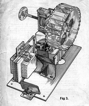
Fig 3 shows the mirror drum, which could be used as a camera or flying spot
scanner. A number of accurately located angled mirrors are affixed to the
circumference of a drum. Each mirror is inclined at an everincreasing angle to
the previous, which allowed scanning to be performed. A modu-lated beam of
light shone onto the rotating mirror surface is reflected onto a viewing surface.
Favoured by the BBC in the 1930's the subject was illuminated by a beam of
light reflected off these mirrors, a photosensitive device would then detect the
light, which had been reflected off the subject. Because of the infra red
sensitivity of the photo sensors creative makeup was needed on the artists to
obtain decent pictures. The flying spot scanner technique is still used in
broadcasting today to convert film to video for transmission. This is often
referred to as teleciné.
Mirror Screw
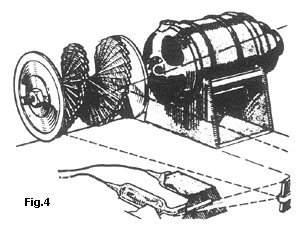
Figure 4 shows the mirror screw arrangement, a series of strips of metal with
polished edges mounted in a spiral staircase arrangement. Normally used as a
receiving device it could produce a fairly large display. A modulated light
source is projected on to the mirror screw. When the rotat-ing shaft is
synchronised to the incoming video source the reflection off the mirrors when
viewed from the front of the mirror will produce a picture. We do not recommend
beginners taking on this project as the positioning of the mirrors and the
quality of the polishing and the black-ness of all other sur-faces is critical
to get good results.
Cathode Ray Tube
Original 'tube' based television, although the 'final nail in the coffin' for
mechanical television, can now be used for NBTV operation. Turning the CRT on
its side to correct for portrait orientation and by changing the deflection
speeds it can accept the 30 or 32 line signals. Likewise a standard vidicon
camera can be converted for direct NBTV application.
Modern digital electronics make it possible to convert standard CCIR-based video
signals into NBTV video. Now normal TV cameras and camcorders can be used to
generate NBTV video signals. In the same way a scanconverter can be made to
convert NBTV video into CCIR video signals. Then a normal video monitor or even
a TV can display the NBTV picture.
Modern Components
Much of the technology today would not have been available to the original
pioneers. High-brightness LED's replace neon lamps; sensitive semiconductors
replace the original photo-multipliers. Experiments with CRT's, LCD's and even
photosensitive welding goggles have been investigated for use with NBTV. Many
people visiting various historic sites around cannot have missed the beauty of a
laser light show or have viewed one in a nightclub. Commercial lasers,
originally prohibitively expensive, are now available to the experimenter as
shown at a recent convention by Colin Hopper. Although we strongly recommend
that they are used by persons competent in their use for safety reasons, these
can be pressed into operation for NBTV use. By varying the intensity and
deflection of the laser a picture can be projected on the wall.
Personal Computer
The modern day Personal computer (PC) can be employed to perform most of the
tasks carried out by the more conventional equipment described above. Several
early attempts were made using the old Spectrum and BBC computers. As PCs
became more powerful many successful programs were written to display, store and
transmit NBTV pictures. Windows based BASIC packages were often used because the
available processor speed was generally offset by the constraints of overheads
of Windows based programs. These programs often required a hardware interface
between the parallel printer port of a PC and the NBTV source, but more recently
it has become possible to use the PC's internal sound card to decode the audio
NBTV signal.
In addition to the display of live NBTV signals, it is possible, e.g. using
programs from Gary Millard, to scan-convert and store NBTV signals (in both B+W
and colour) that originate in a variety of video file formats.
Some club members favour the fully computerised approach to NBTV, but many
prefer to retain a mechanical element in the system. However, there is no doubt
that computers can be of great assistance in providing source material and
playback facilities for the testing and development of both mechanical and
electronic NBTV equipment.