Website for television and imaging using mechanical, radio and early electronic systems.
| Website for television and imaging using mechanical, radio and early electronic systems. |
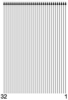
Club standardNumber of frames per second: 12½Number of lines per frame: 32 Number of lines per second: 400 Line scanning direction: vertical, bottom to top Frame scanning direction: horizontal, right to left Viewing position on disc: right Rotation direction of disc: anti-clockwise Picture orientation: portrait Picture aspect ratio: 3 : 2 |
 |
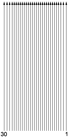
Baird standardNumber of frames per second: 12½Number of lines per frame: 30 Number of lines per second: 375 Line scanning direction: vertical, bottom to top Frame scanning direction: horizontal, right to left Viewing position on disc: right Rotation direction of disc: anti-clockwise Picture orientation: portrait Picture aspect ratio: 7 : 3 Note: In the Baird Televisor the first three lines and the last three lines were made wider and placed more apart. This resulted in an aspect ratio of the viewed total picture of almost 2 : 1 |
 |
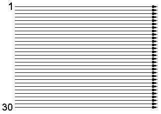
German (TeKaDe) standardNumber of frames per second: 12½Number of lines per frame: 30 Number of lines per second: 375 Line scanning direction: horizontal, left to right Frame scanning direction: vertical, top to bottom Viewing position on disc: top Rotation direction of disc: clockwise Picture orientation: landscape Picture aspect ratio: 3 : 4 |
 |
 |
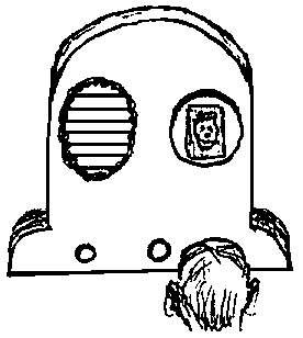 |
| Right-handed camera | Right-handed monitor |
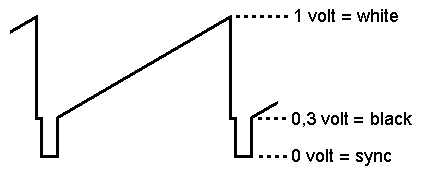
| Video amplitude: Video polarity: Video bandwidth: Note: Sync pulses: Note: Line pulse width: Frame sync: Frame blanking: Note: |
1 volt peak to peak. white is more positive signal, black is more negative. 2 Hz to 10 kHz, at -3 dB. for the Baird standard the frequency bandwidth is theoretically 13 kHz. 33% to 50% more negative than video black, sometimes called "blacker than black" or "ultra black". AC-coupled video will have a black level voltage that floats up and down, depending on the mean picture brightness. DC-restoration or clamping may be done to stabilise the black level voltage. 0.1 to 0.25 msec. line sync pulse missing between line 32 and line 1. during the missing sync pulse the video is black. Baird never used "ultra-black" sync pulses, but a normal black bar between all lines. This gave him problems in synchronisation when a black picture was transmitted. Therefore black pictures were never permitted. |
| Cable: Connector: at equipment: at cables: colour for video: colour for audio Output impedance: Input impedance: |
screened, phono cable or coax. Phono or RCA type, female, male, yellow, white or black, red, all in line with the audio equipment standard. low, 500 Ω or less. high, 5 kΩ or more. |
| Sample rate: Mode: Rec. level video: Rec. level audio: Channels: |
44,1 kHz. stereo, 16 bits per sample (CD-standard). at play-back the line output should give a signal according to the video standard. -10 dB, peaks to -2 dB. video on left, sound or separate sync on right. |
| AM pos Polarity: Mod. depth: Bandwidth: |
positive, white is the largest HF amplitude. 95%, sync HF amplitude is 15% of max. HF amplitude. 20 kHz. |
| AM neg Polarity: Mod. depth: Bandwidth: |
negative, sync is the largest HF amplitude. 90%, white HF amplitude is 10% of max. HF amplitude. 20 kHz. |
| FM Polarity: Deviation: Bandwidth: |
positive, white is the highest frequency, sync the lowest. 15 kHz sync to peak white. 35 kHz, occupies 3 channels in the 12½ kHz grid. |
|
Sample rate: Bits per sample: Mode: Type of file: |
44,1 kHz 16 stereo, video on the left channel .WAV |
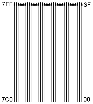
EPROM'sFor the preparation of EPROM's with the help of a computer some specific types of binary files are in use.Number of bytes per line: 64 Order of bytes: according to the NBTV scanning, first byte (number 00) is botttom right, byte number 63 (3F) is top right, last byte (number 7FF)is top left. |
 |
|
Bit allocation: File extension: Examples: Sync position: Sync polarity: Frame sync: Blanking: |
MSB shifted - first letter the use of msb bits: P for still pictures, V for moving video, - number of msb bits used for video, - second letter indicating the use of the remaining lsb bits: S for sync, C for PCM audio, D for delta modulation audio. .P8 : still pictures, 8 bits/pixel, bits 7...0, .P7S : still pictures, 7 bits/pixel, bits 7...1, sync on bit 0, .V6D : video, 6 bits/pixel, bits 7...2, bits 1 & 0 delta mod., .V5C : video, 5 bits/pixel, bits 7...3, bits 2…0 PCM audio. on the first 3 bytes of a line, bytes xx0, xx1 and xx2. bit = 1 indicates sync, bit = 0 indicates active line. the sync of the first line (addresses 0, 1 and 2) should be zero (missing sync pulse). during sync all video bits should be zero, preferably the last byte of each line should be zero, this provides a front porch, during the missing sync pulse the video is preferably blanked. |