Chapter 20
Optics and lenses
Lenses play an important role in the field of NBTV, firstly to form an image
which can be scanned and secondly to concentrate all the available light in the
right place. Image formation is quite easy to understand because if the lens is
not in the right place a fuzzy image is obtained, but the use of a lens in
concentrating light is not always clearly understood.

A simple convex lens is a piece of glass, or plastic, with spherical surface on
one or both sides. More complex lenses are made with two or more convex lenses
but the same principles apply to these also. Take a lens and a piece of white
card and using a distant object focus a clear image on the card and measure the
distance from the card to the centre of the lens. This distance is called the
FOCAL LENGTH (f) of that particular lens (Fig. 1).
Now if (u) is the distance of the object from the lens and (v) is the distance
of the resulting image from the lens then these are all related by the 'lens
formula':

You have just made the object distance (u) very large and so the reciprocal is
negligible and (v) is equal to (f). The image is formed at the focus of the
lens.

Fig. 2 is a ray diagram for a typical point on the object; the diverging rays
from the point are all converged by the lens on to a point on the image. This
occurs for all points on the object thus giving an extended image which, in this
case, is smaller than the object. As the object is brought nearer to the lens
the image recedes from the lens and gets larger. At a distance of twice the
focal length the image is the same size as the object and is at the same
distance. Bringing the object still closer causes the image to recede from the
lens and become much larger than the original object.
By considering similar triangles in fig. 2 one can define the magnification (m)
as follows:

The f-number
The lens is essentially a gatherer of light and its efficiency is often measured
in terms of the diameter of the lens compared to its focal length. If the
diameter is equal to f / 4 then this is often quoted as an 'f 4' lens. The lower
the f-number the greater is the diameter of the lens and the greater its
efficiency as a gatherer of light.
A lens used to create the image for scanning should have an f-number no higher
than about 4, i.e. the diameter should be at least a quarter of the focal
length.
When a lens forms an image of a distant object it does so in the 'focal plane',
but this is an ideal situation. In practice, with a simple lens, the image is
distorted at the edges due to 'spherical aberration', so try and check that your
lens is producing a good image over the whole of the scanned area.
The condenser lens
Let us assume that we are using a Nipkow disc in an NBTV camera. This disc
should be placed in the focal plane of the lens for distant objects, see fig 1,
and the lens is then moved away from the disc to produce clear images of nearer
objects. From fig 1 it can be seen that the light getting through the scanning
holes is diverging and if a small photoelectric cell such as a phototransistor
is placed behind the disc then most of the light will not reach it.

A second lens system named 'condenser' is therefore placed behind the disc to
concentrate the light. It is the placement and action of this lens, which is
often not clearly understood. We want all the light which comes through the
imaging lens to reach the photocell so it is usual to have a 'condenser lens'
which treats the imaging lens as an object and produces an image of it on the
photocell. See fig. 4. Of course the disc will block out a lot of the light but
the general principle still holds.
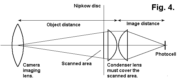
But this is not the whole story. The size of the image on the photocell compared
with the diameter of the imaging lens is in the same ratio as the image and
object distances in fig 4. So if our imaging lens is about 50 mm diameter and
our photocell is only 5 mm in diameter we must have the object distance equal to
ten times the value of the image distance. This implies a 'condenser lens' of
very short focal length and also having a diameter large enough to cover the
scanned area of the disc. This is usually achieved by using a pair of
plano-convex lenses as shown in figs. 3 and 4.
An old slide projector
Notice that the arrangement is very similar to the optics used in a slide
projector, which operates in reverse, the lamp being in the same position as the
photocell. Here the requirement is that the maximum amount of light shall go
forward through the projection lens and a small concave mirror is placed behind
the lamp to increase its intensity in the forward direction. If you can manage
to pick up an old slide projector you have got a ready-made optical system which
is almost ideal for NBTV.
Just remove the rear mirror and put the photocell where the lamp was previously
located. The only snag is the question of whether the 'condenser lens' is
concentrating all the light on the required area. To check this, cut out a hole
in a piece of cardboard with the same diameter as the imaging lens, place a
piece of thin white paper over the hole and illuminate it with a torch. Remove
the imaging lens and place this illuminated 'object' in its place. Remove the
scanning disc and put a small piece of white card in the place where the
photocell is going to go and examine the image of the circle. How large is it?
Will it fit on the photocell you are going to use?
An extra condenser lens?
If the image is too large then an extra lens behind the condenser could be used;
the image will now be in a different place and the white card must be moved
until the image is clear. Putting in an extra lens in this way may raise other
problems as each component of the optical system absorbs some light and there is
the remote possibility that the extra efficiency gained will be offset by the
loss of light due to absorption in the extra lens. In general, it is much easier
if one uses a photocell with an active area of reasonable size rather than a
phototransistor whose active area is very small.
Note that the condenser lens must have a diameter at least as great as the
diagonal of the scanned area.
A drum instead of a disc
In the case of a drum camera the same rules apply but the optical axis is turned
through a right angle by reflection.
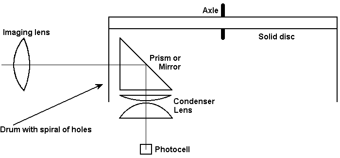
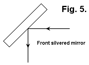
There are three ways of reflecting a beam of light :
1. Using a surface silvered mirror.....
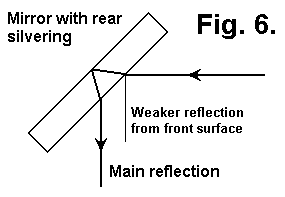
2. Using a rear silvered mirror........
3. Using a prism...........................
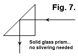
Methods of fig. 5 and fig. 7 are to be preferred. With a rear silvered mirror
there is a possibility that reflection can also take place from the front
surface and mul-ti-ple images can be formed. This is especially true for bright
objects such as a lamp or a candle flame. It is not often a serious problem with
the sort of scenes which are found in front of the NBTV camera.


